


Home page >> Product display >> Special testing machine >> HYYL-4000 multi-oil circuit dynamic hydraulic loading system
1. Project Overview
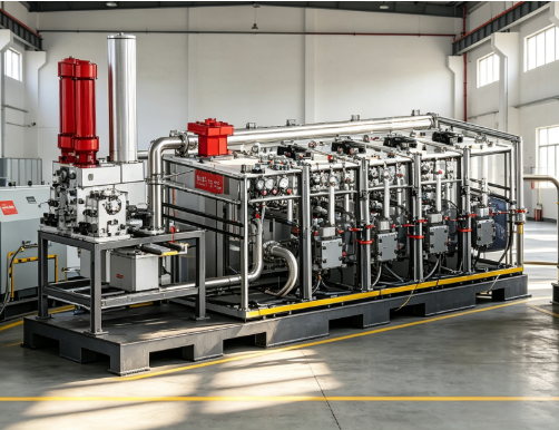
This project builds a multi-oil circuit dynamic hydraulic loading system and supporting dynamic hydraulic station cooling system. The system includes high-performance linear actuators, hydraulic pump stations, fully digital closed-loop control systems, host computer workstations, actuator sliding guides and complete cooling auxiliary systems.The equipment can realize force closed-loop, displacement closed-loop dynamic fatigue, and static loading tests. It supports a variety of standard waveforms and customized waveform outputs. It has complete data collection, monitoring, alarm protection, and external linkage capabilities. It can meet the testing needs of components such as static load, dynamic load, and fatigue cycle. It strictly follows all technical index requirements of the bidding documents.
2. Overall system architecture
The entire system consists of two subsystems: a multi-oil circuit dynamic hydraulic loading host system and a dynamic hydraulic station cooling system.
Multi-oil circuit dynamic hydraulic loading host system: high-performance linear actuator, servo valve group, hydraulic pump station, full digital controller, host computer workstation, actuator sliding guide, sensor group, high-pressure pipeline, alarm protection unit;
Dynamic hydraulic station cooling system: cooling tower body, axial flow fan, spray pump, main water supply pump (one for use and one for backup), auxiliary pump unit, water storage tank, stainless steel cooler, pipeline valves and fittings, water collection and spray components.
System working logic: The hydraulic pump station outputs high-pressure oil to drive the linear actuator to perform the loading action; the fully digital controller collects load and displacement signals, and adjusts the servo valve through the closed-loop PIDF algorithm to achieve force/displacement closed-loop control; the host computer completes test parameter setting, waveform editing, data storage, and curve display, and can be linked with the tester's comprehensive management and control system; the cooling system performs constant temperature control on the working oil temperature of the hydraulic station to ensure long-term continuous dynamic testing of the system.
3. Detailed technical plan of multi-oil circuit dynamic hydraulic loading system
3.1 Main components of the system
This system mainly consists of high-performance linear actuators, hydraulic pump stations, fully digital closed-loop control systems, host computer workstations, 400t reaction force sliding guide rails, high-pressure hydraulic pipelines, sensors, servo valve groups, and audible and visual alarm units.
3.2 Control mode and linkage function
Control mode: Supports three control modes: dynamic force closed loop, dynamic displacement closed loop, and dynamic open loop;
Operation mode: local manual control panel operation + linkage control with the tester comprehensive management and control system;
Operation functions: Complete test key parameter setting, test start/stop, test key information monitoring, data storage and export, and realize all test functions.
3.3 Control system monitoring and display functions
The controller and supporting software can monitor and display the following test parameters in real time:
Basic test quantities: test force value, displacement value, dynamic load value, static load value;
Waveform parameters: control the upper and lower peak values of the waveform, operating frequency, number of cycles, and cumulative test time;
Graphics function: real-time tracking and drawing of force-time curves and displacement-time curves. The curve interface supports zooming and partial viewing.
3.4 Control system collects hardware indicators
Adopting an industrial-grade fully digital controller, all channels of load, displacement, and strain are configured with a 32-bit fully digital waveform generator:
Data acquisition frequency ≥10kHz;
Built-in signal generator output frequency ≥500Hz;
Frequency resolution ≤0.01Hz.
3.5 Dynamic control response parameters
Control algorithm: fully closed-loop digital control, P, I, D, F control parameters are all adjustable, adapting to different specimen stiffnesses;
Closed-loop control rate ≥ 6kHz;
Hardware sampling rate ≥10kHz;
Communication interface: Ethernet communication between the controller and the host computer, transmission rate ≥100Mb/s;
Program waveform generation frequency range: 0.001Hz ~ 500Hz;
Expansion capability: ≥3 expansion channels are reserved to facilitate the later addition of sensors or expansion of actuating units;
Physical synchronization output: The control cabinet is equipped with a hardware synchronization output interface, which has 1 channel of force, 1 channel of displacement, and 1 channel of deformation synchronous data physical output, which can be used for synchronous collection by external devices.
3.6 Security warning and protection functions
The system collects hydraulic system pressure, working oil temperature, tank level, and system flow signals in real time. When the parameters exceed the set threshold, the following protection logic is executed:
Sound and light phoenix sound alarm prompt;
Automatic load reduction and shutdown protection when exceeding the limit to prevent damage to equipment and test pieces;
Supports custom settings for protection threshold software, and automatically records logs of protection events.
3.7 High performance linear actuator
Project | Technical parameters |
Number of actuators | 1 set |
Installation posture | Supports installation and fixation in horizontal, vertical and any spatial postures |
Rated dynamic load | ±4000kN, the overall relative indication error of the system is <1% |
Actuation stroke | ±250mm |
Test force starting range | 2% 100%FS |
Displacement sensor | Resolution 0.001mm, indication error ±0.5%F.S; |
load cell | 5000kN, dynamic indication error ±1%F.S, static indication error ±0.5%F.S; |
Working frequency | 0.01Hz 10Hz, can complete fatigue cycle loading |
Output waveform | Sine wave, cosine wave, square wave, triangle wave, sawtooth wave, supports user-defined waveform import and output |
3.8 Hydraulic pump station
parameters | Indicator requirements |
Total output flow of pumping station | ≥400L/min |
System working pressure | ≥21MPa |
Servo valve performance | The flow rate is 500LPM, the maximum working pressure is 350Bar, the maximum flow rate of the pilot valve is 8.6LPM, and the sinusoidal anti-seismic acceleration is 10g; |
Drive motor configuration | 45KW×5 units, total power 225KW |
High-pressure oil circuit filtration accuracy | ≤10μm |
Filtration accuracy of oil return pipeline | ≤3μm |
Equipment noise | The noise of the whole machine is ≤72 decibels |
High pressure pipeline | The standard pipeline length is ≥20m and can be adjusted and customized according to the on-site layout of the laboratory |
3.9 Actuator sliding guide
Equipped with an actuator sliding guide rail with a reaction force carrying capacity of 400t, the actuator can be slid and positioned along the guide rail direction to meet the adjustment of the installation position of different test specimens. The guide rail is equipped with a locking mechanism to reliably lock during the loading process.
3.10 Workstation and software system
Computer hardware configuration
Operating system: WIN10 64-bit and above;
Memory: ≥8GB RAM;
Hard drive: dual hard drive 2×500GB;
Monitor: ≥23-inch LCD monitor.
Software operating environment: All operating software runs based on Windows system.
Software function
Integrated digital oscilloscope interface;
Digital display of test parameters;
Real-time data plotting;
Users can freely configure the interface layout and display channels;
Test data storage, playback and export;
Alarm event log recording;
It can realize linkage communication with the comprehensive management and control system of the test instrument.
4. Technical solution for cooling system of dynamic hydraulic station
The cooling system is used to take away the heat generated by the continuous operation of the hydraulic pump station, ensure that the temperature of the hydraulic oil is stable within a reasonable range, and ensure long-term continuous operation of dynamic loading.
4.1 Overall performance indicators
Total cooling flow ≥60 m³/h;
Total cooling capacity ≥300000 kcal/h;
Oil temperature control stable range: 40℃-55℃, the temperature control target can be set in the software.
4.2 Pipe diameter configuration
The pipe diameter of the main water inlet and outlet is ≥DN80;
The pipe diameter of water supply inlet and sewage outlet is ≥DN25;
Overflow pipe diameter ≥ DN40;
A complete set of pipelines with valves, joints and seals.
4.3 Fan unit
Equipped with a total of 2 dedicated axial flow fans for cooling towers:
Single motor power ≥2.2KW;
The air volume of a single machine is ≥28000 m³/h.
4.4 Spray pump group (2 units)
Single motor power ≥2.2KW;
Silent design;
Motor: fully enclosed splash-proof and dust-proof outdoor motor, which can be installed indoors and outdoors;
Pump seal: mechanical seal structure, anti-leakage, easy to maintain;
Pump body: Epoxy-coated precision casting pump body with high strength and long life.
4.5 Main water pump (2 sets, one in use and one in standby)
Single machine power ≥7.5KW;
Flow rate ≥60 m³/h;
Lift ≥30m;
It has the function of automatic switching of backup pumps in case of failure.
4.6 Auxiliary pumps (2 units)
Single motor power ≥2.2KW;
Flow rate ≥60 m³/h;
Lift ≥30m.
4.7 Water storage tank
The overall dimensions of the water tank are not less than: 500mm in length × 1000mm in width × 1000mm in height. It is equipped with liquid level observation, water replenishment, sewage discharge and overflow interfaces.
4.8 Cooler
The cooling and heat exchange tube specifications are ≥Φ22×0.8mm, and the material is 304 stainless steel, which is corrosion-resistant and has high heat exchange efficiency.
4.9 Spray water collection component
The water collector, spray pipe and sprinkler head are made of PVC / PPR / U-PVC / PVC / ABS material, which is resistant to water corrosion and aging.
5. Description of the main functions of the system
Static loading test: complete static tension and compression loading, collect force-displacement curves, and complete static mechanical performance testing of components;
Dynamic fatigue loading test: output sine, triangle, square wave, sawtooth and custom waveforms, conduct cyclic fatigue tests, and record the number of cycles and fatigue damage;
Multi-closed-loop control switching: Force closed-loop and displacement closed-loop can be switched online to adapt to various types of specimens with large stiffness differences;
Safety protection: Fengming alarm when pressure, oil temperature and liquid level exceed limits, automatic shutdown, protecting actuator, servo valve and test piece;
Data record export: All original data, curves, and alarm logs can be saved, and export in Excel and other formats is supported;
System linkage: supports local operation, and can also be connected to the laboratory's comprehensive management and control system to achieve remote linkage;
Hardware synchronous output: Force, displacement, and deformation hardware synchronous output can be used for synchronous sampling by external acquisition equipment;
Temperature control guarantee: closed-loop temperature control of the cooling system ensures stable oil temperature for long-term uninterrupted dynamic testing of the system.
6. System supply scope list
serial number | Equipment part name | Quantity | Remarks |
1 | ±4000kN high performance linear actuator | 1 set | Contains built-in displacement sensor |
2 | 5000kN load cell | 1 set | Dynamic + static measurement |
3 | High performance servo valve group | 1 set | Includes matching valve block |
4 | Hydraulic pump station (225KW total power) | 1 set | Complete set of filters, accumulators and sensors |
5 | Full digital control system controller | 1 set | 32-bit waveform generator, 10kHz acquisition, synchronous output interface, ≥3 reserved channels |
6 | PC workstation (including monitor, system software) | 1 set | Win10 64, 8G, dual hard drive 500G |
7 | Actuator sliding guide rail (400t reaction force load) | 1 set | With locking mechanism |
8 | High pressure hydraulic pipeline components | 1 set | ≥20m, can be adjusted on site |
9 | Fengming alarm and protection unit | 1 set | Pressure, oil temperature, liquid level, flow monitoring and protection |
10 | Dynamic hydraulic cooling system cooling tower body | 1 set | Includes 304 stainless steel cooler |
11 | Axial fan | 2 units | Single machine ≥2.2KW |
12 | Spray pump | 2 units | Silent fully enclosed motor |
13 | Main water supply pump (one for use and one for backup) | 2 units | 7.5KW, 60m³/h, head 30m |
14 | Cooling auxiliary pump | 2 units | 2.2KW, 60m³/h, head 30m |
15 | Cooling water tank | 1 set | ≥500×1000×1000mm |
16 | Cooling system pipeline valves and fittings, sprinkler heads, water collectors | 1 set | PVC/PPR/U PVC material, complete interfaces for each pipe diameter |
17 | Installation auxiliary materials and cables | 1 batch | Connecting cables and connectors between devices |